This is the next post in my Fondusi’s Development Blog series. Click here to check out week 3 or start at the beginning.
Week 4 – August 22nd – 28th
This week we focused on getting the lighting system working in the tile engine. In order to do this, I had to change the way the tile engine was being rendered. Read on to see how we did it and how it looks.
Lighting
My plan for the lighting, object composition-wise, was to have Light objects that would be attached (i.e. in a List
So, the first thing I did was go about creating textures for my Lights. They looked like this:

Great! We had a light texture, I just needed to figure out how to use it. That should be easy right? Well, eventually I came up with a plan and now the lighting works like this:
- On the draw call, a List<Light> object is created.
- During the tile draw loop, each tile is checked to see if it has any Lights associated with it. If it does, the Light objects are appended to the List<Light>.
- The tiles are drawn onto the tile RenderTarget2D.
- After the tile loop, the list of Lights is iterated through and drawn on their own RenderTarget2D.
- The GraphicsDevice is then set back to drawing to the backbuffer.
- We use a custom shader and pass in the lighting surface as a parameter and draw the tile RenderTarget2D to the screen.
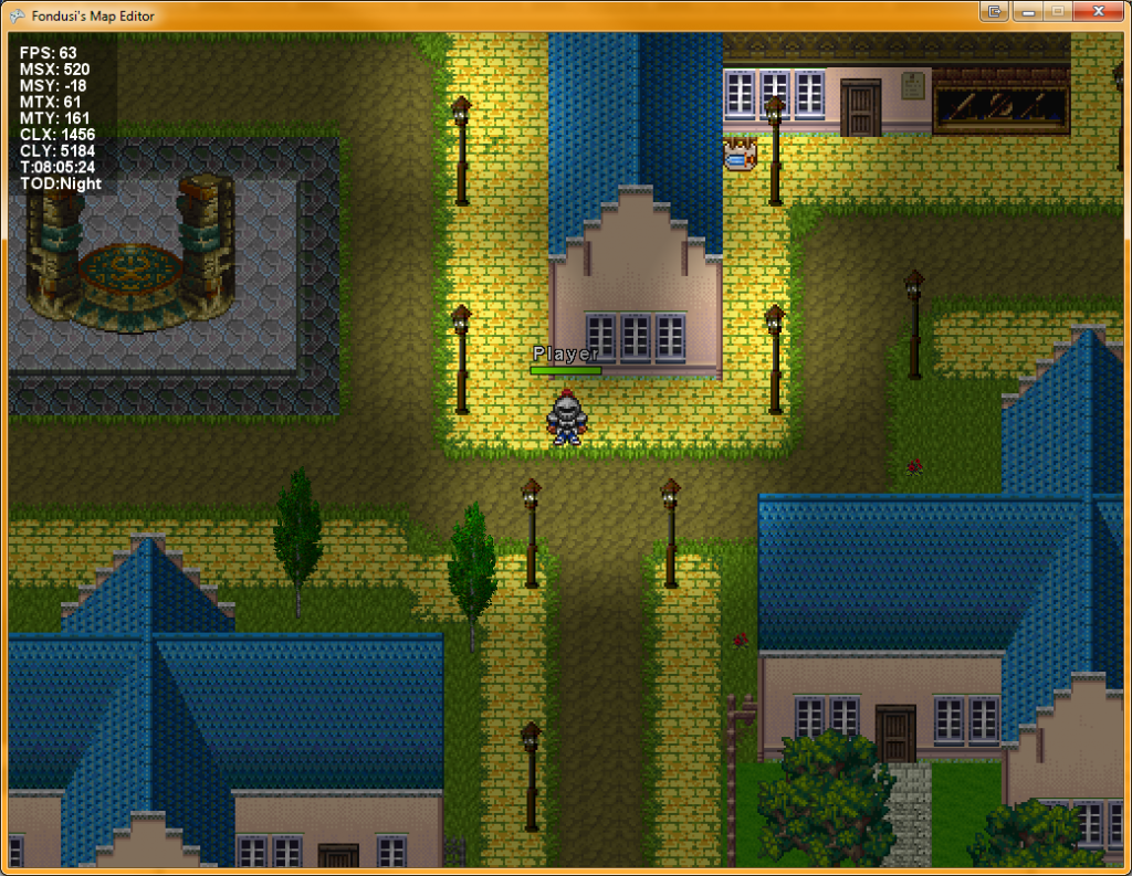
This all worked out just great. No problems at all. Nope. Nadda. No even one. Okay fine, there was one tiny hitch that I will discuss in another blog post, but before I go on, here’s a screenshot of the final outcome:

Lighting Shader
The custom lighting shader serves two purposes:
- It handles the screen “darkness.” It does this by accepting a float value to multiply all pixel rgb channels by. For example, if you pass in 0.75, all rgb values for all pixels will be multiplied by 0.5 and so, they will get closer to black, making the scene appear darker.
- It determines how the lights affect said “darkness.” It does this by sampling the lighting surface and determining how much the float should actually affect a pixel.
If you’re wondering how the second one works, I’ll explain. Heck, I’ll explain even if you’re not wondering. 🙂
The lighting surface is grayscale and has colours that range from black (0) to white (1) based on the texture shown above and where it was drawn. Now, in the pixel shader, we sample the pixel colour from the main surface (the one with the tiles and players and such in it) and the colour from the lighting texture for the same pixel. Without the lighting system, we would just take the colour from the main surface and multiply it by the darkness multiplier.
Now, if you think of the lighting values (remember they’re essentially just between 0 and 1) as a percentage, we wanted the darkness value to affect a pixel based on that percentage. So, if a pixel in the lighting surface is all white, the darkness multiplier will not be applied. If a pixel in the lighting surface is black, the darkness multiplier would be fully applied. If a pixel on the lighting surface had a value of 0.5, we would only want the darkness multiplier to be applied at 50% of it’s strength. And so on.
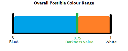
I’m assuming a darkness multiplier value of 0.75, a lighting pixel colour of 0.5 and I’m going to use the following diagram to help me explain it. Hopefully it will make things a bit more clear.

What we want to do is apply the lighting pixel value as a percentage of the orange section above, where a lighting pixel value of white (1) = 1 and a lighting pixel of black (0) = 0.75. The first step we need to do is figure out how big the orange section is. We can do that by using this:
1 - DarknessMultiplier = 0.25.
Next, we need to figure out the lighting percentage which we’re going to multiply against the value we just got. The trick here is that the lighting has to be subtracted from 1 because we want a value of white (1) to equal 0 darkness, and multiplying 1 * 0.25 = 0.25 so that’s no good. Our percentage is 1 - LightingPixelValue = 0.5. Cool. We figured out just how much of that orange value we want to keep (0.5 – 50%).
We then multiply our orange section’s size by our percentage: 0.25 * 0.5 = 0.125. Now, we need to figure out the total change we’re going to apply to the pixel’s main colour by taking this number and subtracting it from 1. 1 - 0.125 = 0.875 This number is then multiplied against the main rgb values to get the final pixel colour.
So finally, after writing a bunch of things down and fiddling with this, we came up with this formula:
|
1 |
Color.rgb = Color.rgb * (1 - (1 - DarknessMultiplier) * (1 - LightingPixelValue)); |
I also just realized that you could also do it this way:
|
1 |
Color.rgb = Color.rgb * (DarknessMultiplier + (1 - DarknessMultiplier) * LightingPixelValue); |
But I’ll let you figure that one out. 😛
The Rest
Here’s a list of the things we worked on this week:
- Added fill layer option
- Fixed some bugs with the particle engine code
- Added environmental controls to editor form
- Added some new particle emitters
- Added new render target for lighting
- Moved tile engine draws onto their own render target
- Added lights to the map class
- Added ability to add and edit lights on the map
- Added pixel shader for drawing the lighting render target over the main tile render target
- Added some new textures for the lighting/light editing
Whew. This post took a long time. So long that I’m almost due for another. Well, see you next time!


Is it possible to get a solution / project that shows this technique with the associated .fx effects. I am trying to do something similar and hitting a wall with the implementation.
It’s been a while, but I’ll see what I can do. Is there anything in particular you’re having an issue with?